ABSTRACT
This project implements a phase-synchronous FM synthesis algorithm in hardware. Envelope and low frequency oscillator modulation of oscillator parameters is implemented. The microcontroller the system is based on, the XMOS XS1-G4, allows for physical parallelism including features such as multiple cores, multiple hardware threads on each core, a hardware event-driven thread scheduler, and channel, channel ends, and link switches for thread and core communication.
The event-driven architecture of this device was ideal for implementing this synthesis algorithm. The final product is portable, durable, has a simple, intuitive user interface, and allows for extensive spectral shaping capabilities. The basic functional requirements outlined were successfully implemented. Testing, however, revealed a dynamic range that is out of specification. Some methods of reducing analog and digital noise are proposed in the Conclusions section.
BACKGROUND
Classic analog synthesizers rely on the principle of subtractive sound synthesis to generate sound. This involves taking a spectrally rich waveform, and applying subtractive (low pass, high-pass, and bandpass) filters to customize the output frequency spectrum, and thus the “timbre.” This architecture has been carried forward into the digital domain, where it is a fairly efficient synthesis technique. However, this project will implement an algorithm associated with the digital domain, and rarely implemented in the analog domain, frequency modulation synthesis.
REQUIREMENTS
Functional Requirements
1. At least one oscillator capable of generating spectrally dense waveforms with wave-shape options and minimal undesirable artifacts (aliasing, heterodyning, etc…)
2. MIDI control
3. Spectral shaping with resonance capabilities
4. Amplitude and oscillator parameter modulation envelopes
5. Low-frequency oscillator modulation of amplitude and oscillator parameters
6. Parameter adjustment via knobs, buttons, and display.
DESIGN APPROACH ALTERNATIVES
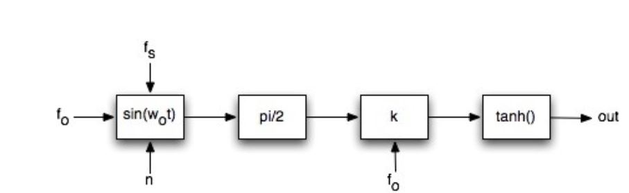
Figure 4.2: tanh Square Generation
Tanh waveshaping uses the concept of distortion synthesis to generate a square wave. The tanh() function, a sigmoid, is overdriven by a sine wave, and a square wave is approached as the sinusoid encounters soft, nonlinear clipping. The input signal is a pi/2 scaled sine wave.
PRODUCT DESIGN
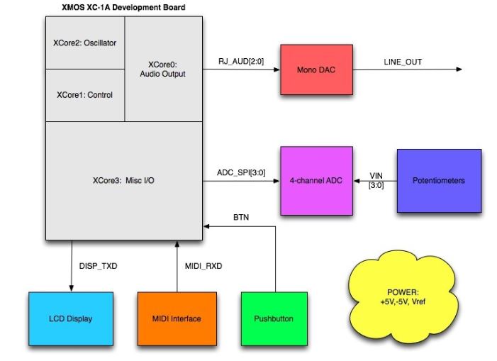
Figure 5.4: Overall System Block Diagram
The DAC chosen for this system is the 16-bit DAC8580 manufactured by TI. This DAC was chosen because it provides up to 16x oversampling, doesn’t use noise shaping, and doesn’t require an external buffer to drive line loads. These features reduce the need for the microcontroller to run at high sample rates in order to push image frequencies farther up the frequency band.
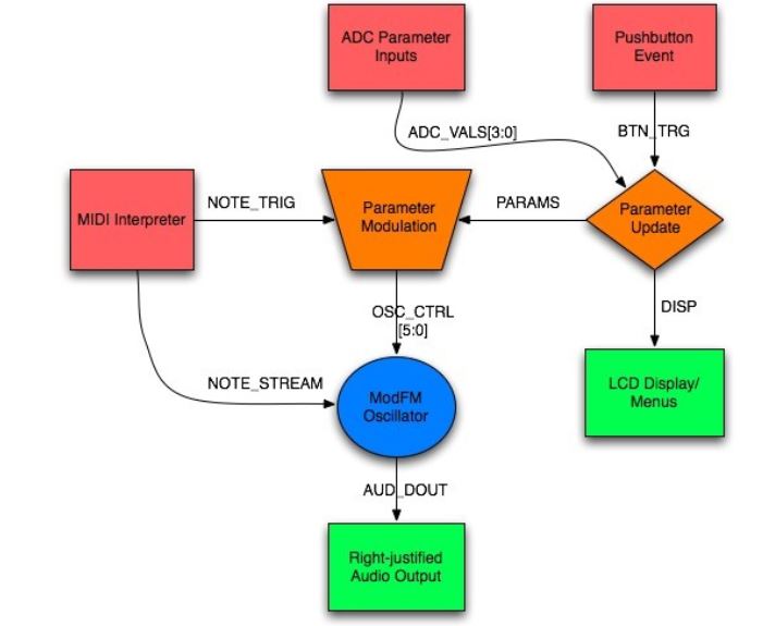
Figure 5.9: Software Subsystem Block Diagram
The general software flow of this system begins with events generated by hardware abstractions of input peripherals. These input events are handled in the parameter control subsystems which are also passed applicable data values. Control data is streamed to the oscillator, which streams audio data to the right-justified audio output hardware abstraction. Parameter and menu state data from the control subsystems is sent to the LCD display hardware abstraction, which handles state change and parameter update events.
PHYSICAL CONSTRUCTION AND INTEGRATION
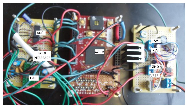
Figure 6.1: Photograph of Board Implementation
Circuit Board Implementation
1. Breadboard style perf-board with point-to-point soldered connections (saves time and money for prototype vs. custom PCB, component count is low)
2. Components distributed among three boards:
◦ Power: provides +/- 5 V supplies as well as a reference source for the DAC
◦ Microcontroller: the XMOS XC-1A development board breaks out all available I/O and includes a prototyping area which will be used to house the DAC
◦ Peripherals: a separate board will be used to house the MIDI hardware and ADC chip
INTEGRATED SYSTEM TESTS AND RESULTS
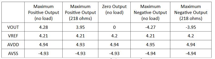
Figure 7.1: Power Supply/DAC Load Testing
The power supply was first tested with a zero DAC output and no load on the DAC. Then maximum positive and negative digital values were sent to the DAC and tests were conducted with no load, and a low impedance load. For each test, the DAC output, reference, AVDD, and AVSS voltages were recorded using a multimeter. Low impedance DAC loads had no effect on supply voltages. The low impedance load loaded the DAC, but in a predictable way (the low impedance load tested is comparable to the output impedance of the DAC).
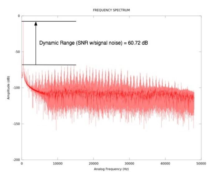
Figure 7.4: Frequency Spectrum of 440 Hz Cosine Output
The DAC was tested by outputting a cosine wave, calculated on a once-per-sample basis, to the DAC. Correct operation was verified (the output signal was in the shape of a cosine and no overflow or clipping was present). The dynamic range (or SNR in the presence of a signal) was tested by recording a 440 Hz cosine output to a raw WAV file (resampled at 96 kHz) and generating a frequency spectrum in MATLAB.
CONCLUSIONS
This project was successful in meeting most functional requirements initially proposed. The system is capable of generating spectrally dense waveforms with extensive spectral shaping capabilities and resonance control. Parameter modulation functions are available for all oscillator parameters. The user interface provides a minimal, yet intuitive menu system for the adjustment of parameter settings, with visual feedback. A line output is available, and there is no perceptible audio latency. The product is small, portable, and relatively durable.
However, the oscillator algorithm appears to exhibit aliasing, especially at parameter extremes. There is currently no method of bandwidth control implemented, so high values of k in combination with large carrier to modulator ratios or large fundamental frequencies have no guarantee of being band- limited. Even with a cosine output, undesirable harmonics above the average noise floor are present.
Source: California Polytechnic State University
Author: Justin Tomlin
>> More Matlab Projects on Signals and Systems for Students
>> 200+ Matlab Projects based on Control System for Final Year Students
>> More Analog Communication Projects using Matlab for Final Year Students
>> More Matlab Mini Projects for Engineering Students