ABSTRACT
This project investigates methods for calibrating and functional testing an Engine Vibration Measurement Equipment. The equipment uses accelerometers to measure vibrations on the JAS 39 Gripen aircraft engine to ensure that the engine is correctly installed. A model for emulating the electronic signals generated by the accelerometers was created in Simulink and different ways for utilizing the model as a part of a complete test system were examined.
Upon examination of different calibration methods it was found that a complete test system needs to have the ability to both send electrical signals directly into the EVME as well as a way of testing the accelerometers mechanically. Both short and long term solutions fulfilling these requirements were prepared.
THEORY
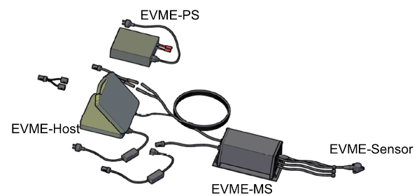
Figure 2: Overview of the EVME
The EVME is used to control the engine and gearbox vibration levels after installation and during service. The EVME consists of four main units; one unit named EVME-sensor consisting of four accelerometer, one signal processing unit named the EVME-MS, the presentation computer named EVME-host and the EVME-PS which supplies power, see figure 2.
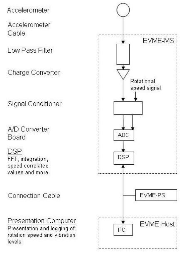
Figure 3: Simplified schematic of the EVME
The EVME-MS contains a number of electronic components that process the accelerometer signals and performs the relevant calculations. Since the interesting spectra for the Gripen engine is in the interval of 70 Hz – 2000 Hz, the accelerometer signals are processed by a low pass filter with a cut off frequency of 2000 Hz. The filter also protects components from harmful high frequency signals.
The signals are then amplified and processed by a charge converter which converts the signals from pC to mV. After the charge converter a signal conditioner is used to adapt the signal to the A/D converter. The A/D converter digitizes the signals with a sampling frequency of 6400 Hz, see figure 3.
RESULT
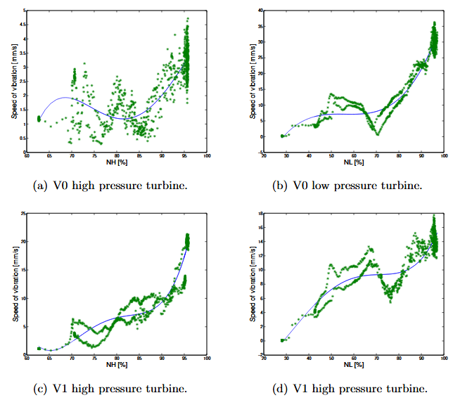
Figure 6: Graphical representation of the approximations used for two of the accelerometers, where green represents the imported data points and blue is the fitted curve
In order to generate vibration signals in the same magnitude as the engine vibrations, data from previous engine test runs was used. This gives information on how the speed of the vibration corresponds to the rpm of each engine turbine, NH and NL, respectively. The data was imported to MATLAB from a .xml-file and the embedded function polyfit() was used to create a fitted curve of fourth order accuracy. The speed that each accelerometer signal represents is then calculated with the coefficients of the fitted curve. In figure 6 four of the approximations are shown.

Figure 7: Simulink model
The purpose of the Simulink model is to generate and store signal data that subsequently can be used to generate electrical signals. In the model each accelerometer is represented by an embedded function block in which the output signal is calculated according to the signal design, see figure 7. The model uses NL as input and in addition to the emulated accelerometer signals, the vibration speeds for the low- and high-pressure turbine as well as the total vibration speed are returned for each accelerometer.
DISCUSSION
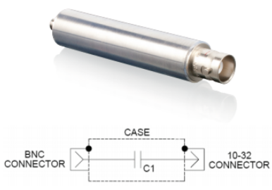
Figure 9: The 2947C Calibration Capacitor
The accelerometers used by the EVME produce very small charge signals when excited. To emulate these the Endevco 2947C Calibration Capacitor can be used, see figure 9. The 2947C is a 1000 pF capacitor that converts a voltage in the order of mV to a charge in the order of pC. This makes it ideal to use together with a microprocessor and a DAC to construct a freestanding accelerometer emulator.
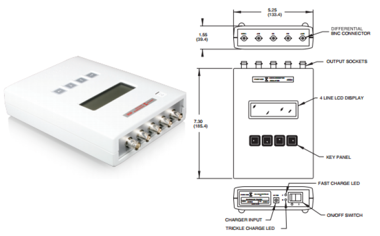
Figure 10: The Endevco 4830A Portable Simulator
The 4830A portable simulator, shown in figure 10, is a battery operated instrument that is used to simulate a number of outputs from various types of transducers. It is in many ways fit to test the functionality of the EVME since it can produce single ended charges in the frequency interval 1 – 10 000 Hz, which includes all the frequencies that the EVME is exposed to. The 4380A can provide the outputs in acceleration, velocity or displacement, which makes for easy detection in any discrepancy between the input velocity and the velocity calculated by the EVME.
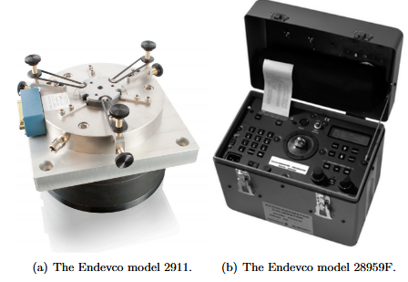
Figure 11: The two accelerometer calibration products considered
There are different products designed for calibrating accelerometers that could be used for testing the EVME. These sorts of calibration systems are not designed for the specific task of testing the EVME, yet could be used for the purpose. Two products for calibration have been reviewed, seen in figure 11.
CONCLUSION
There are efficient methods for testing and calibrating the EVME both electronically and mechanically. It was decided that the optimal solution would be to have a combination of the two; an electronic simulation system that could create complicated multi-tone signals to test the electronics in the EVME-MS, and complement it with a simpler mechanical vibrator to verify functionality of the entire system with the accelerometers connected.
The EVME could be adequately tested using the 4830B in combination with a speaker component for a complete system verification, as described in section 5.3.2 and 5.4.1 respectively. This combination is a recommended method for testing the EVME and could be utilized in the Saab Support & Services laboratory in the near future.
For a long-term solution it is recommended to further develop the c-code framework that can be generated from the Simulink model. Continued work would enable the possibility to construct a separate device or incorporate the simulation system in the next generation EVME, as described in greater detail in section.
Source: Uppsala University
Authors: Ludvig Backlund | Anna Martin | Gustaf Svantesson
>> Huge List of Matlab Projects with Free Source Code
>> Matlab Project Topics List with Free Pdf for Mechanical Students
>> More Matlab Projects on Signals and Systems for Students
>> 200+ Matlab Projects based on Control System for Final Year Students
>> 80+ Matlab Projects based on Power Electronics for Final Year Students