ABSTRACT
The purpose of this project is to continue the work on a vehicle model developed in ADAMS/Car and applied with the concept of ACM (Autonomous Corner Module). The project is divided up in two parts.
The objective of the first part is to setup a co-simulation environment between ADAMS/Car and MATLAB/Simulink, and evaluate the vehicle model. In the second part a yaw controller is developed using only the rear wheel steering possibilities. The controller will be evaluated when it is applied on the vehicle model.
The approach is to develop two models, one simpler in MATLAB/Simulink and one more complex in ADAMS/Car, and verify that they show similar behavior. The models will then be linearized and the control design will be based on the most appropriate linear model. Most of the work has been developing and evaluating the two vehicle models in ADAMS/Car and MATLAB/Simulink.
The result was a working co-simulation environment where an evaluation of two different controllers was made. Due to linearization of the ADAMS model was unsuccessful, the controllers were based on the simpler linear Simulink model. Both controllers show similar results. Tests on the ADAMS model showed that it is hard to control both the yaw rate and body slip only by rear wheel steering.
AUTONOMOUS CORNER MODULE
The Autonomous Corner Module (ACM) was patented 1998 and is a wheel corner that is individually powered and has computer controlled propulsion, braking, steering, spring and damper functions. The unit is supposed to be identical on the left and right front axle as well as the left and right rear axle. It has two mechanical interfaces with the body of the vehicle via the suspension arms. The rest is based on the idea of x-by-wire 1 technique.
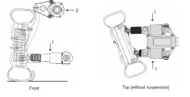
Figure 2.1.Overview of an Autonomous Corner Module, where (1) is steering actuators and (2) rotational spring-damper system
ENVIRONMENT
Co-Simulation
By combining ADAMS/Car and MATLAB/Simulink it is possible to, for example, add control algorithms to a model developed in ADAMS/Car. The synchronized simulation of the two systems is called a co-simulation. In order to set up a co-simulation environment ADAMS/Car has to be provided with two modules, ADAMS/Controls and ADAMS/Solver. The ADAMS/Controls module generates a simulation model based on the ADAMS/Car model, which can be imported into Simulink. ADAMS/Solver’s purpose is to calculate the result from the equations of motion. During a co-simulation, a closed loop between the ADAMS/Car model and the control system is formed, see Figure 3.2.
ADAMS/Car inputs of a model enter the ADAMS/Solver, which calculates the output signals from the model. The ADAMS/Solver output signals enter the control system, where MATLAB calculates the control signals, and a new iteration starts by sending the control signals as inputs to the ADAMS/Car model. The ADAMS/Solver module is a numerical analysis application that automatically solves the equations of motion for kinematics, static and dynamic simulations for an ADAMS/Car model. The result of the co-simulation can be imported into ADAMS/Car, where plots and animations from the simulation are available.
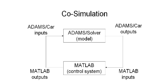
Figure 3.2. The principle of co-simulation between ADAMS/Car and MATLAB
ADAMS MODEL
This chapter will describe a vehicle model that is developed in ADAMS/Car, and therefore named the ADAMS model. The model will serve as a foundation for evaluating developed control algorithms and was originally created in a previous work, although not completely evaluated. The following sections will describe the structure of the ADAMS model, while the corrections and tuning work will be discussed in Chapter 6. A section with a brief description of how the model is set up in a co-simulation environment is also provided.
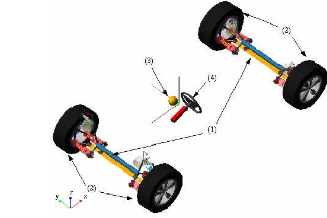
Figure 4.1. Full vehicle assembly of the ADAMS model
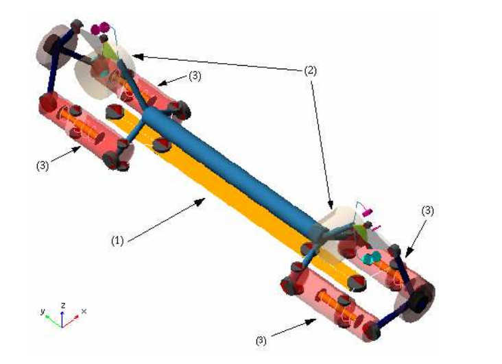
Figure 4.3. The axle template of the ADAMS model
SIMULINK MODEL
In this chapter another vehicle model is derived. The model will have the possibility to set individual steering angles, in line with the concept of ACM, but in a more simple way compared with the ADAMS model in the previous chapter. The mathematical equations of the model are implemented and simulated in MAT- LAB/Simulink, see Section 3.2, and therefore the model is named the Simulink model. The reasons for developing the Simulink model are
1. To get understanding of the dynamic behavior in subsystems of the vehicle, such as suspension and tire forces.
2. If the model behaves similarly to the ADAMS model, then the models are most probably reliable. The comparisons between the models also ease the process of finding modelling errors.
3. To examine the possibility to use it in the development process of the control system.
MODEL EVALUATION
The ADAMS and Simulink models will be used to design and evaluate the latter control system. A comparison between the two models is made in order to detect modelling errors. This chapter also deals with the driving scenario used for evaluation of the ADAMS and Simulink model, and thus, also for the latter yaw rate control system.

Figure 6.6.Upper plots: Lateral and normal force on each wheel of the ADAMS model. Lower plots: Lateral and normal force on each wheel of the Simulink model
ACTIVE YAW CONTROL
The concept of ACM opens the door to many new possibilities in the aspect of control systems. This chapter describes two different yaw rate controllers that have been developed during this project. Controlling the yaw rate means controlling the speed of rotation around the z axis of the vehicle’s coordinate system, see Section 5.2. The driver of a vehicle has learned to feel the car dynamics under the normal operating conditions. But in critical situations, like slippery roads or a flat tire or an unexpected strong side wind, he notices that he does not master the vehicle’s yaw motion and may react in a wrong way. A yaw controller would, in this case, have a stabilizing effect and the driver would hopefully not feel the change of condition.
The objective for a yaw rate controller is not only to keep the vehicle stable in abrupt braking maneuvers and high speed cornering, but also when the surface of the ground is slippery. The two controllers derived in this chapter are only working under the circumstances of small front steering and slip angles. Therefore it might be enough that the compensated yaw is generated by the use of the steering possibilities in the concept of ACM. More abrupt breaking and steering maneuvers are considered to be in a different driving mode, for example collision avoidance, and may be solved using individual wheel breaking.
The solution of the controllers is based on the fact that the driver is in complete control of the front steering angles, thus the aim for the yaw controllers are to make the intended driving maneuver successful by using only the rear wheels steering possibility. If the controllers are able to stabilize the non-linear ADAMS model, when subjected to the lane change maneuver presented in Section 6.1, they are considered successful. A comparison between two driving situations is evaluated, one on a firm surface and one on a slippery surface.
CONCLUSION
The conclusions of this project are divided into the parts Autonomous Corner Module, vehicle models, and control design. Each part also includes remarks on recommendations for future work.
Autonomous Corner Module
The concept of the Autonomous Corner Module enables many possibilities, not only in the aspect of safety and environment, but also additional features to make the vehicle more appealing. The steering actuators make it possible to set both camber and steering angle. However, the focus in this project has been on stabilization of the vehicle using the four wheel steering and therefore the possibility to control the camber angle has been neglected. Other interesting control systems for the future, in line with the concept of ACM, are an active suspension system and side wind and road slope compensating systems. The combination of these control systems are also worth to study, design and evaluate.
The ADAMS and Simulink Model
Due to an acceptable behavior by the ADAMS model in a co-simulation environment, the first two problems from Section 1.3 are considered solved. An acceptable behavior is based on the fact that the signals in the ADAMS model resemble the model implemented in Simulink. Further improvement that can be done on the ADAMS model is to remove unnecessary details on the upper arm. These details make the model more complex than needed, which can lead to numerical problems when working with the model. Another component that also can be adjusted is the flexible body. Today it is not pre-tensioned, which forces the rotational spring-damper system to carry more of the load than it is supposed to.
Control Design
The linearization result of the ADAMS model affected the structure of the project, see Section 1.4, and therefore the two methods of developing the control system are not possible to compare. This linearization problem makes it not possible to design a control system based on an ADAMS/Car complete vehicle model. The linearization problem and the fact that the Simulink model corresponds with the ADAMS model, results in that the linear Simulink model is used in the control design.
Source: Linköping University
Authors: Daniel Westbom | Petter Frejinger
>> Automobile based Matlab Project Topics with Free Base Papers Downloads
>> MATLAB Project Ideas and Titles for Electrical & Electronics Engineering Students
>> 100+ Easy Electronics Projects for Engineering Students
>> More Matlab Projects on Signals and Systems for Engineering Students
>> 200+ Matlab Projects based on Control System for Final Year Students
>> More Matlab Mini Projects for Final Year Students