ABSTRACT
When simulating target seekers, there is a great need for computationally efficient, target models. This report considers a study of radar target modelling based on Inverse Synthetic Aperture Radar (ISAR) measurements of generic aircraft. The results underlie future modelling of full-size air targets.
A method is developed for two-dimensional modelling of aspect-dependent target scattering. The approach taken is to generate point-scatterer models of two targets, where each point scatterer is defined according to its position and radar cross section (RCS), estimated from ISAR images. The scattered energy contributions from all point scatterers are summed to simulate a radar return signal. To validate the models, the modelled radar target centre is compared to the true radar target centre, which is determined from ISAR images.
The method is presented to be promising for modelling air targets with large, persistent radar cross section.
BACKGROUND

Figure 2.1. Bistatic Radar System
A typical radar system consists of a transmitter and a receiver, where the transmitter operates by radiating electromagnetic energy towards a target. When the target becomes illuminated, it reflects energy that can be observed by the receiver. Most radar systems do not transmit and receive at the same time, thus a single antenna can be used on a time-shared basis for both transmitting and receiving.
Such a radar system is said to be monostatic. When different antennas are used for transmitting and receiving, the system is called bistatic. The strength of the reflections depends on the size of the target, its shape and electrical conductivity. Particularly strong reflections are obtained from metallic objects, such as ships and aircraft. Figure 2.1 illustrates the concept of a typical, bistatic radar system.
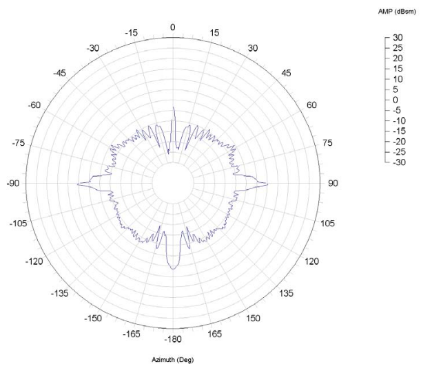
Figure 2.4. Typical RCS plot of an aircraft target
An aircraft target is very complex. It has many reflecting elements and shapes. The measured RCS of real aircraft varies significantly depending on its direction to the illuminating radar. Figure 2.4 shows a typical RCS plot of an aircraft. Here the radar is operated at X-band frequencies using horizontal polarisation for both transmitting and receiving. The target is represented by the generic model-aircraft Rak, described. The plot is an azimuth cut made at zero degrees elevation.
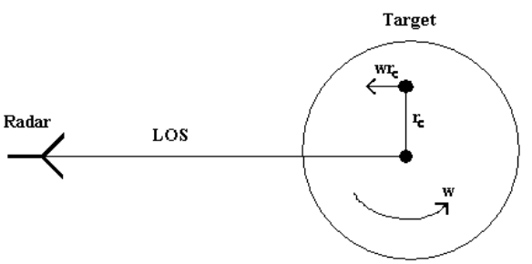
Figure 2.6. Velocity of rotating scatterer
Consider a single scatterer located on a rotating target (figure 2.6). It is assumed that the radar line-of-sight is in the rotational plane of the scatterer. The target rotates at a fixed angular rate of ω rad/s about an axis perpendicular to the line-of-sight. A scatterer at a cross-range distance rc will have an instantaneous velocity ωrc toward the radar. A doppler frequency shift will result, given by

where fc is the carrier frequency and c is the propagation velocity (speed of light) of the radar signal.
METHODOLOGICAL CONSIDERATIONS
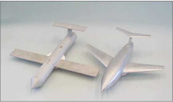
Figure 3.1. Rak (left) and Rund (right)
There are two different objects, or targets, observed in the study. Both are generic model aircraft, constructed by The Swedish Defence Research Agency, FOI. The targets, named Rak and Rund are about one metre long and shown in figure 3.1. They are built from metal, without any moving parts or cavities. Their radar cross sections have been measured outdoors in advance of this study.

Figure 3.2. Rak on tripod
The RCS measurements of Rak and Rund were carried out in year 2000, by Saab Bofors Dynamics and the FOI. The targets were placed on top of a styrofoam tripod (figure 3.2), approximately 100 metres away from the antenna. The whole arrangement was placed on a large turntable that rotated with constant angular velocity, while the radar was held stationary. This is the usual appliance for ISAR measurements.
RESULTS AND DISCUSSIONS

Figure 4.2. ISAR image of Rak at 0° (left) and 60° (right)
In figure 4.2 there are two example images illustrating the RCS distribution of Rak at viewing angles 0° and 60°, for HH polarisation. The images are typical for this target. At 0° the majority of the scatter originates from direct reflection from the leading edges of the wings and fin. There are also direct reflections from the stabiliser. Apparently, scattering occurs as both distributed and centred. When rotated 60°, the target image shows directly reflected scatter originating from the left side of the conical nose. The right angle of the wing-attachment constitutes a typical corner reflector with dominant RCS, caused by indirect scattering.
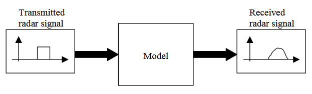
Figure 4.7. Block Model
The model may be considered as a black box with a transmitted radar signal as input and a received signal as output (figure 4.7). The received signal constitutes the radar signal scattered by the target. The purpose of the model is to alter the transmitted signal in a way that it resembles the radar return from actual targets, in this case the generic model aircraft Rak and Rund.

Figure 4.16. Point scatterer positions (left) and errorplot (right)
For certain aspects the target has distributed RCS along one of its wings. This applies when the radar line-of-sight is perpendicular to the edge of a wing. In the range between 0° and 180°, this happens around 35° for the left wing and at 155° for the right wing. When using a single point to cover the distributed RCS, an error is introduced. By placing new points at the tip of the wings, the correctness of the model is increased at these specific angles (figure 4.16), since the distributed RCS is shared between the points.
CONCLUSIONS
This report has presented a method for point scatterer modelling where the proposed method has application to target-seeker simulations. The method has been proved to be best suited for radar targets with large radar cross section. Target scattering localised to bright and persistent scattering centres, is easily modelled by a small number of point scatterers. If some parts of the target are dominating the total radar cross section, for all possible aspects, these regions alone can be considered for modelling.
On the other hand, if the RCS is distributed or varying for different aspects, the complete target area needs to be modelled. Targets with very small radar cross section are on the other hand difficult to model by using the developed method. As described in section 4.5, the Rund model fails to accurately describe the radar target centre for nose-on viewing angles where the radar cross section is so low that it’s hard to distinguish the actual target.
It’s possible to improve the modelling of targets with small radar cross section in different ways. One way is to increase the transmitter power during the RCS measurements, this way the target is more easily detected. Next, background subtraction can be applied when generating ISAR images. If the RCS of the background is measured, it’s possible to subtract this information from the target image.
A few notes can be made about the use of the method for the background purpose of creating radar target models for target-seeker simulations. First of all the method has to be extended to include RCS measurements of full-size objects in three dimensions. Thus, turntable data of real aircraft need to be collected for different elevation angles. Further, raw-data signals from conventional target seekers are necessary for improved model validation, regarding both target positioning and classification.
To sum up, the evaluated method of radar target modelling offers an easy way to produce computationally efficient models of air targets. The big disadvantage of the method is the lack of automation and optimisation when characterising point scatterers.
Source: Linköping University
Author: Andreas Wessling
>> 100+ Easy Electronics Projects for Engineering Students
>> Automobile based Matlab Project Topics with Free Base Papers Downloads
>> Antenna Analysis using Matlab for ECE Students
>> More Matlab Projects on Signals and Systems for Students
>> 80+ Matlab Projects based on Power Electronics for Final Year Students
>> More Matlab Mini Projects for Final Year Students