ABSTRACT
This paper describes the changes made from Cal Poly’s initial railgun system, the Mk. 1 railgun, to the Mk. 1.1 system, as well as the design, fabrication, and testing of a newer and larger Mk. 2 railgun system. The Mk. 1.1 system is developed as a more efficient alteration of the original Mk. 1 system, but is found to be defective due to hardware deficiencies and failure, as well as unforeseen efficiency losses. A Mk. 2 system is developed and built around donated hardware from the Naval Postgraduate School.
The Mk. 2 system strove to implement an efficient, augmented, electromagnetic railgun and projectile system capable of firing an approximate 1g aluminum projectile to speeds exceeding 2 km/s. A novel three part projectile is proposed to mitigate rail and projectile degradation. Projectile and sabot system kinematic equations are derived and the projectile is designed and tested along with Mk. 2 barrel. A numerical electromechanical model is developed to predict the performance of the Mk. 2 system and projectile assembly, and predicts a final velocity for the fabricated system exceeding 3.5 km/s and an efficiency as high as 24%.
Testing of the Mk. 2 system showed catastrophic failure of the projectile during initial acceleration, resulting in very short acceleration times and distance, low velocity projectiles, and low efficiencies. During further testing of various projectile configurations, the barrel structure failed due to a large internal arc. Future work for the Mk. 2 system is discussed, a revised external barrel structure suggested, and a solid, more conventional solid chevron projectile design suggested. Keywords: Electromagnetic, railgun, magnetic, hypersonic, orbital, debris, Cal Poly, rail, gun, augmentation, model, testing.
MK. 1.1: THE STEP FROM INJECTION TO PRESS-FIT
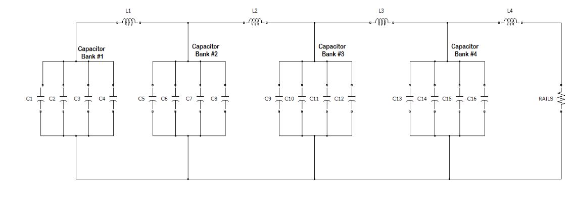
Figure 2-Mk. 1 Power Supply
The power supply for the Mk. 1 system consisted of sixteen 10,000 μF Aluminum Electrolytic capacitors charged to 450 V, with a total stored energy of 16 kJ. The system avoided pulse-capable crowbar diodes by utilizing an inductive PFN (Pulse Forming Network, shown in Figure 2.
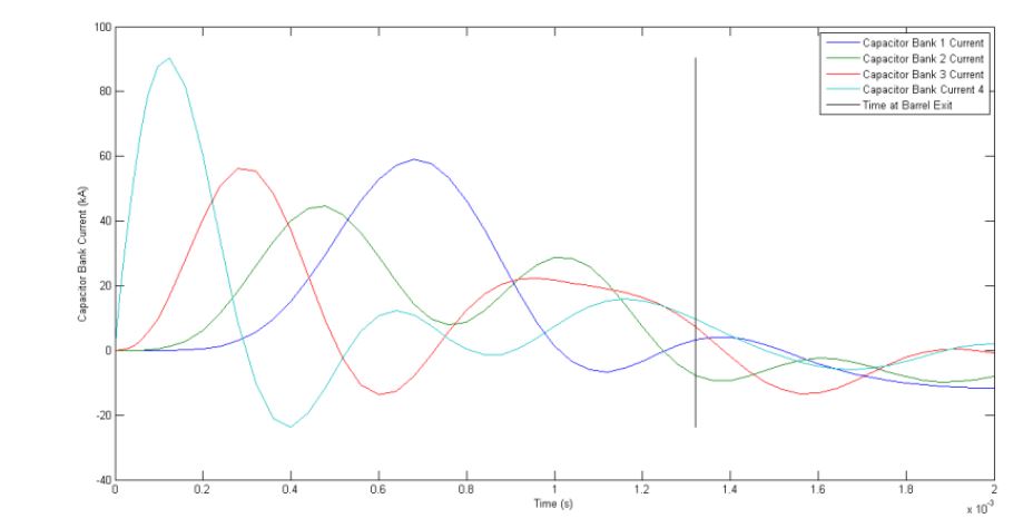
Figure 3-Mk. 1 Simulated Capacitor Bank Currents
This was a very oscillatory system, with complex interactions between each of the banks of capacitors. This complexity has an inherently low stability, resulting in a minimal chance of displaying the theoretical results shown in Figure 3 during a system test.
MK.2 SYSTEM
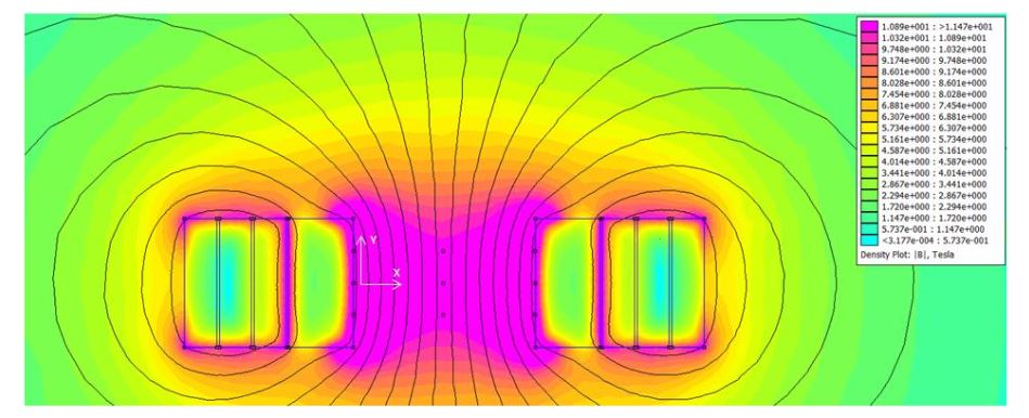
Figure 15-Augmented magnetic field simulation
In order to do this, the magnetic field was averaged in the ‘Y’ direction, shown in Figure 15, by taking the field strength at the top of the projectile and averaging it with the field at the middle of the projectile. The purple regions represent areas of high, > 10T, field strength, whereas blue regions represent areas of low, < 1T, field strength.
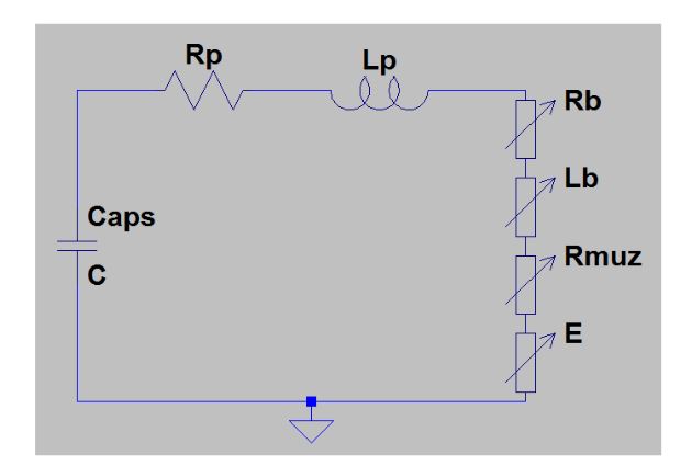
Figure 17-Capacitive Discharge equivalent circuit
The electric circuit model solves for the rate of change of the current through the load during two phases of the pulsed discharge: the capacitive discharge, and the inductive discharge. A circuit schematic of the capacitive discharge portion is shown in Figure 17.
CONCLUSION
In summary, lessons were learned through the failed testing of the Mk. 1.1 system that showed flaws in the data acquisition system and control systems, as well as proved the difficulties of press fit projectiles in small bore railguns. These lessons were incorporated into the Mk. 2 railgun and projectile assembly design, giving effective and reliable data acquisition, as well as leading to the 3 part projectile design.
A model was developed in Matlab to predict the performance of the Mk. 2 railgun system, including the barrel current, projectile assembly velocity and position, barrel magnetic field, and thermal changes in the projectile. The model equations are derived and integrated over time using Matlab’s ODE45 function. The results of this model show velocities exceeding 3 km/s and efficiencies of about 24 %, which is a large increase compared to the Mk.1 efficiency of 0.6%.
Source: California Polytechnic State University
Author: Jeffrey Joseph Maniglia Jr.
>> 200+ Matlab Projects based on Control System for Final Year Students
>> More Matlab Mini Projects for Engineering Students