INTRODUCTION
The main goal of this project is to design and manufacture a testing device that will move an antenna in way that simulates a wingtip in flight in an anechoic chamber for the Raytheon Company. Raytheon is a defense contractor that is divided into multiple divisions including Air and Missile defense, Cyber security, and Electronic Warfare (EW). Raytheon’s EW division in Goleta, CA is developing and producing electronic warfare products such as radar warning receivers and jammers for the US military forces. These devices work through signal triangulation.
BACKGROUND
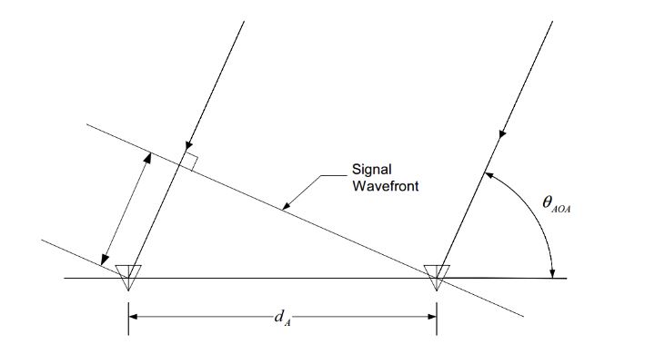
Figure 1: Diagram of emitter location estimation
To locate a signal, multiple antennas are mounted on the aircraft wingtips. These points of reference provide data of the delay between receiving a signal on one detector to the other as depicted in figure 1. This is called the time-difference-of- arrival. This data is combined with the known positions of the detectors to estimate the location of the ground-emitters.
CURRENT SYSTEMS
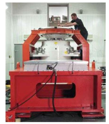
Figure 4: Indistrial vibration driver from Brüel & Kjaer
There are two types of automobile simulation platforms; one type is essentially a scaled up vibration table and the other is a seismic simulation platform that uses electromagnetic and electro-hydraulic exciters. The large scale vibration table has the disadvantage of only being able to output one frequency and the amplitude adjustment is difficult. Some automotive shakers that operate with electromagnetic and electro-hydraulic exciters could get the required motion profile.

Figure 13 . Kinetix 3 Servo Drive
The components in our system that need to be powered include the motor, driver, microcontroller, and encoder or potentiometer. As stated earlier, each motor will be powered by its respective driver or speed controller. The driver we have chosen for the vertical axis, the Allen-Bradley Kinetix 3 drive requires 1 phase, 240 VAC input which can be obtained from 240V wall sockets. Standard microcontrollers need 5V input and can be powered by a USB cable, AC-to-DC adapter, or a battery.
OBJECTIVES
Raytheon develops antennas to be mounted on the wingtips of planes used for radar triangulation systems, which transmit important information to the pilots. The flutter motion of the wingtips in flight decreases the accuracy of the triangulation system, and it is important to be able to predict the location of t he wingtip under flight conditions to more accurately implement signal triangulation.
DESIGN DEVELOPMENT
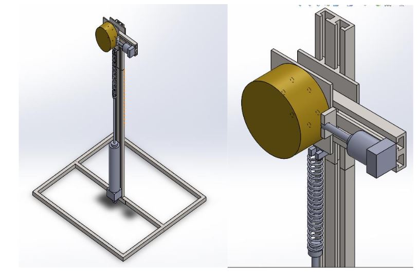
Figure 14 . Draft 3D model of spring-actuator design
This system will be driven by a short stroke mechanical actuator in the horizontal axis and a medium stroke actuator combined with a spring in the vertical axis. The payload will be attached to a carriage that slides along a rail in the horizontal axis. This rail will also be attached to a carriage that will slide along a vertical rail.
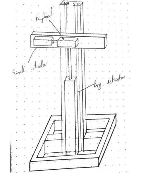
Figure 16 . Sketch of direct driven payload
This system will be identical to the previous system except for the vertical axis will no longer have a spring in it. This concept requires a sufficient budget to purchase an actuator with a long enough stroke and high enough speed to not need spring amplification. This would allow for the vertical axis to be directly controlled just like the horizontal axis, meaning generation of movement profiles would be much easier and faster, as well as more flexible in the kinds of motion it could generate.
FINAL DESIGN
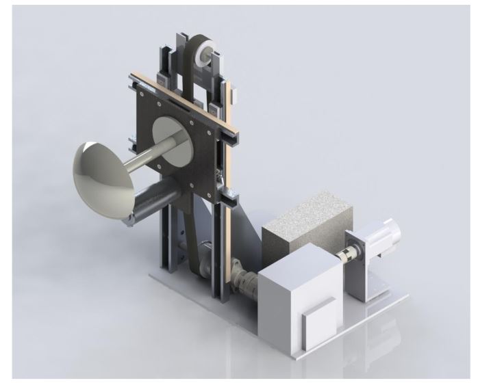
Figure 17. Overview of final system design
The final design for the wingtip dynamics simulator is shown above. The main driving mechanism of the system is a servo motor and belt drive for the vertical motion and a DC motor on a rack and pinion for the horizontal motion. The two axe s of motion for the payload will be independently controlled and a linear encoder will collect data on the location of the payload during the test.
PRODUCT REALIZATION
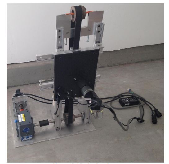
Figure 18. The final product
This project involved a tight integration of both hardware and electronics, thus the manufacturing of the mechanics and development of the electronic drive systems occurred in parallel. This section outlines the process and outcome of the build phase and is divided into sections according to the functional sub-assemblies.
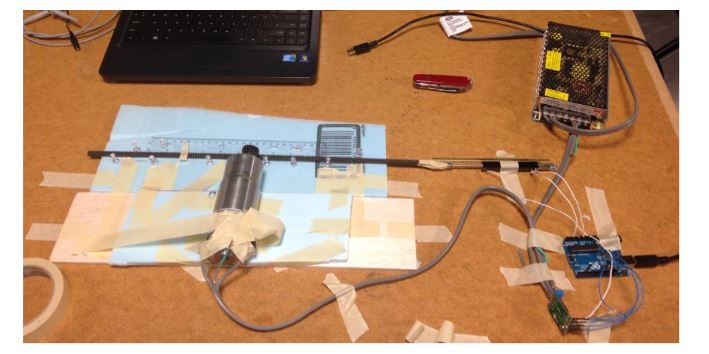
Figure 25. P controller test setup before hard mounting onto base plate
With the position control finalized, a random position generator was created using the random number function inherent in C programming language. The random motion generator is random in the sense that the single next sinusoidal wave’s amplitude and frequency was unpredictable, but there were restrictions on the range of possible amplitude and frequency values to match the project requirement.
DESIGN VERIFICATION
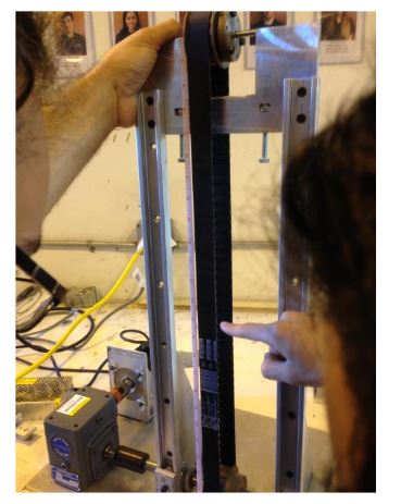
Figure 27. Comparing measured belt travel to desired travel distance
The MotionView software that controls the Kinetix 300 servo drive has a built in user units function. Using it, the ratio of revolutions of the motor to our user units (inches) could be specified. This was calculated to be 2.5 rev/inch by taking into account the 20:1 reduction gear box and the size of the pulley used. This number was verified by commanding the motor to move 10 inches and measuring how far it actually moved via a marked location on the belt.
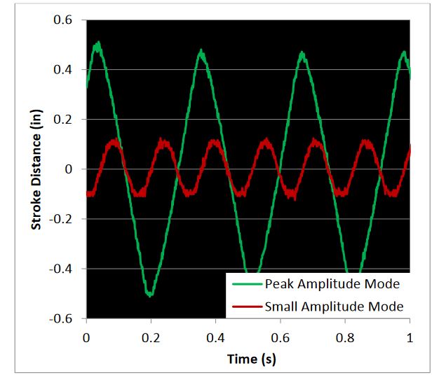
Figure 30. Oscilloscope plot that shows that the horizontal drive system achieves the desired small and large amplitudes and frequencies
To test the horizontal motion response of the baseplate, an oscilloscope was connected to the linear potentiometer to measure the voltage readout while the device was in motion. The two required modes for horizontal motion were first tested independently by running a code that moved the payload in a constant sinusoidal motion.
RECOMMENDATIONS AND CONCLUSIONS
Our wingtip dynamics simulator device successfully met most of the engineering requirements, and for the requirements that we were unable to directly verify, we are confident in our initial design which incorporated large factors of safety, and we expect the device to perform to satisfaction. We have attached a user’s manual in Appendix J that will explain how to configure this device and operate it for testing. Through the process of building and testing the device, we have observed some design choices that may be beneficial for Raytheon to consider and implement and have them listed below.
In the final design, the DC motor was mounted on the payload plate. This resulted in the motor needing to move its own mass in addition to the payload. This configuration also takes up space on the payload plate for mount holes and radio frequency absorbent foam. To remedy this, an attempt was made to mount the motor to the frame, but anywhere it could be mounted would have resulted in a collision sometime during the vertical cycle of motion. In future iterations of this device, an effort should be made to redesign the horizontal drive system so the motor is not attached to the front of the payload plate.
Source: California Polytechnic State University
Authors: Eugene Fox | Nick Rodriguez | Steven Rieber
>> Antenna Design Projects for Engineering Students