ABSTRACT
In this project, we investigate automatic control of a quadrotor UAV and discuss its possible applications in the Smart Building. The purpose is to construct a control algorithm for stable quadrotor flight and explore the use of UAV in a smart home. We derive the equations of motion for a quadrotor, construct a model and devise a control strategy to keep it stable in the air. The strategy will be to use cascaded controllers for position and attitude.
Simulations are performed and the controllers are then tested in practice. In the simulations, we use lead lag controllers as they provide easy loop shaping and good performance. In the practical implementation, we instead chose to implement PID controllers, due to their wide use in industry, easy implementation and ease of tuning. The end result is a stable loop with acceptable performance in terms of positional control. A simple waypoint system is implemented as well, which is key for trajectory planning and enables the vehicle to perform various tasks.
SENSORS
A couple of sensors are required in order to keep a quadrotor stable; these are at the very least: accelerometers and gyroscopes. Readings from these sensors can be used to estimate the current attitude. The gyroscope is required in order to detect the angular speed, while the accelerometer corrects the gyroscope for drifts in sensor output, as well as in stationary provide a direction for earth’s gravity.
In addition to the sensors required for stabilization, more sensors are of course of interest, such as for determining position via GPS or measuring real world attributes such as temperature and pressure.
- Accelerometer
- Gyroscope
- Cameras
MATHEMATICAL MODELING
Now, a mathematical model of the quadrotor is developed. The model will be a basis for how to use the measured values from the sensors in order to control the quadrotor.
- Coordinate transformations
- Quadrotor forces and torques
- Dynamical equations
- Linearization
- Transfer functions
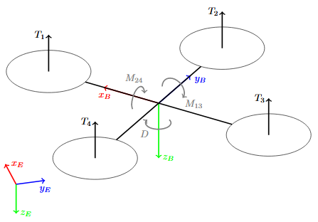
Figure 1. Schematic over forces and torques acting on a quadrotor
The forces and torques acting on the quadrotor that are deemed sufficiently large to have an effect, are all from the 4 motors. See Fig. 1 for reference. The total thrust in the body- fixed z direction is the sum of the force generated from the 4 individual motors,
T = T1 + T2 + T3 + T4
CONTROL
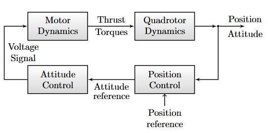
Figure 2. Outline of control system used for automatic control of quadrotor movement
We now design controllers for the quadrotor movement using the linearized model. The control system will consist of two sets of cascaded controllers: one for position control and one for attitude control. The first set will include controllers for each of the inertial coordinates x, y and z. Likewise, the attitude control consists of controllers for the Euler angles φ, θ and ψ. The basic outline of the control system can be seen in Fig. 2. We will only perform a detailed design of the position controllers and leave a brief explanation of how attitude control can be performed.
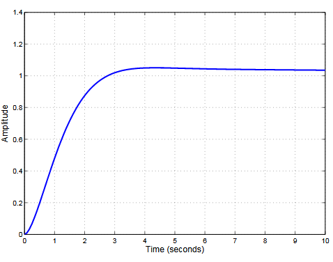
Figure 3. Step response in the y-direction for the horizontal controller
The step response is shown in Fig. 3. The overshoot is ≈ 5% , the rise time ≈ 1 . 8 s and the settling time ≈ 23 . 5 s. The overshoot is low at the cost of a long settling time. This is suitable for path tracking applications as long as the UAV does not need to reach its goal in a short time. Therefore, the designed controller is deemed sufficient. As specified, the input angle must be ensured to be bounded.
SIMULATION
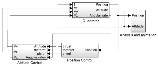
Figure 7. Simulink model
In the simulation, the cascading control strategy discussed earlier is employed which make use of the designed controllers from the linearized model. The model can be seen in Fig. 7 The values for moment of inertia are taken where measurements have been done on the quadrotor in the Smart Mobility Lab, and are given by

EXPERIMENTAL IMPLEMENTATION
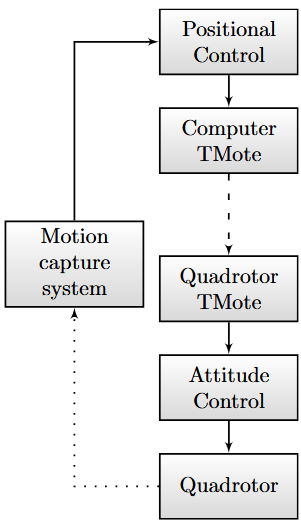
Figure 10. Overview of data flow in the lab. Dashed lines represent wireless connections, dotted lines optical observations, solid lines represent normal connections
The flow of data in the lab can be seen in Fig. 10. The positional controller in LabVIEW retrieves data from the motion capture system and uses this together with the current positional setpoint to send a reference signal for throttle & attitude. The reference signal is sent through the Tmote link to the quad, upon which the attitude controller reacts to the reference signal and aligns the quadrotor to it.
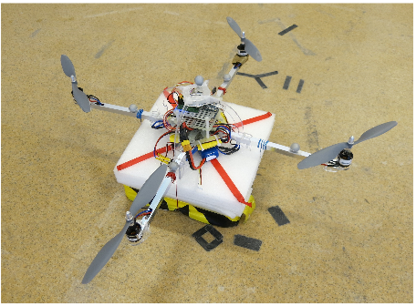
Figure 11. The quadrotor used for experimental implementation
The throttle value was then, together with attitude signals corresponding to the quadrotor being level, prepared to be sent when a button for safety descent is pressed. When these signals are sent, the quadrotor descends in a moderately quick pace and lands with the correct side down, where a styrofoam base protects all parts from impact. See Fig. 11 for a picture of the quadrotor flown in the lab, including the protective styrofoam base.
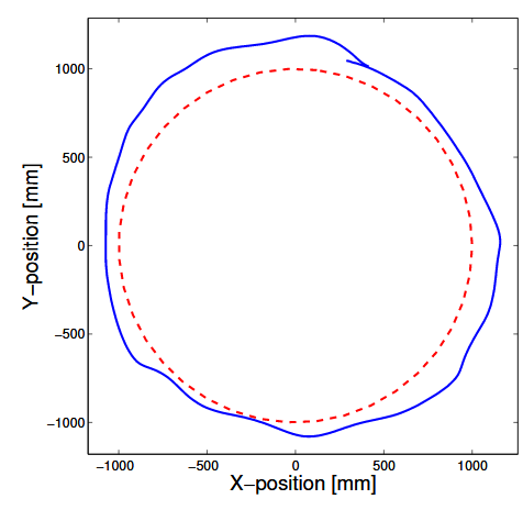
Figure 16. Quadrotor (blue) following a reference circle (dashed red)
The waypoint system was used for testing real-world step characteristics and the ability to fly in various geometric shapes such as circles and squares, as well as altitude changes in combination with large yaw-changes. Reference tracking of a circle split into 40 waypoints can be seen in Fig. 16. The flight was performed at an altitude of 1 . 3 m. The radial RMS error for one revolution was 124 mm, which is declared as adequate for the quadrotor’s purposes.
DISCUSSION
As could be seen in the simulations as well as in the experimental results, the control strategy seems viable for practical use. The quadrotor could follow simple paths with relatively small error.
The assumption that the positional variables are decoupled and independent of each other when the attitude is horizontal is not entirely correct. Positional changes in the x and y direction simultaneously showed signs of coupling between the controllers as the quadrotor took longer to reach its setpoint. The coupling between x and y in the lab can be explained to some extent by the quadrotor in the lab not being as symmetrical as expected.
APPLICATIONS
Since quadrotors, especially of this size and up, are quite noisy, their use for the smart building is mostly outdoors where they could fly at an altitude high enough to decrease the disturbance felt by people on the ground. With cameras mounted to quadrotors, they could be used outside as mobile security cameras, tracking a target and transmitting video to an operator.
For example, in the case of a break-in, the quadrotor could follow the villain and report position and video feed to local authorities. A UAV could vastly outperform a fixed camera network for tracking a moving target, as it will be able to keep the target in view at all times, which would be very expensive to do using stationary cameras. However, monitoring has ethical implications in case of misuse, such as someone spying on innocent civilians via the quadrotor.
CONCLUSION
In this project a mathematical model of a quadrotor was created. It was then used as a base for simulations that continued on into an experimental implementation. The experimental implementation produced a control system capable of holding the quadrotor in a desired position, as well as a waypoint system and necessary safety features. In brief, the cascading control strategy could be implemented as a commercial product that have various applications in the smart building.
FUTURE WORK
It would be interesting to have used only on-board components for controlling the quadrotor, as no other sensors than those needed to keep the quadrotor stable were mounted and installing other sensors was deemed to be out of the scope of this project. On board sensors that keep track of the quadrotors position is essential if the purpose is to fly outdoors, as the camera system would not be available.
Future work done on quadrotors in the SML that utilizes LabVIEW could benefit from using our framework built up around security and ease of use, in order to shorten development time. A more in depth theoretical study could also be carried out. The model and simulation can be improved by for example including more disturbances. Such work could benefit from using the constructed simulation since it can easily be extended.
Source: KTH
Authors: Daniel Sjoholm | Martin Biel
>> Automobile based Matlab Project Topics with Free Base Papers Downloads
>> Matlab Project Topics List with Free Pdf for Mechanical Students
>> Simulink Projects using Matlab for Engineering Students
>> 200+ Matlab Projects for Control System for Final Year Students
>> More Matlab Mini Projects for Engineering Students
>> More Wireless Mini Projects for Engineering Students