ABSTRACT
Walkers provided stability to the elderly but cannot assist a person from sitting to standing. The objective of this project is to present the design and analysis of a lift assist walker. This report discusses the design and analysis of a collapsible lift assist walker capable of lifting a patient up to 250 lbs. from seated to standing in under 10 seconds. The designed walker utilized a two stage scissor mechanism with a gas spring assisted embedded linear actuator.
MECHANICAL SYSTEM DESIGN
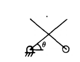
Figure 9: T he angle theta referred to in this document is the angle the scissor makes with the horizontal
To maintain claims on the intellectual property, the two stage scissor mechanism and U-Shape had to be maintained. Prior to selecting an actuation mechanism, the force to lift a load was determined using statics for a two stage scissor mechanism with a horizontal actuator. The stage at which this horizontal actuator is placed does not affect the lift force generated. The force F is constrained to the horizontal, W is the weight of a patient and the angle theta is shown in Figure 9.
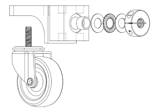
Figure 13 : Front bearing block shown with caster. This assembly is similar to the mid bearing block
The front bearing block is designed to support the power screw and incorporate a front caster. Figure 13 shows an exploded view of this front bearing block. The section where the caster is bolted on is intentionally thick to enable the wheels to be level.
ELECTRICAL SYSTEM DESIGN
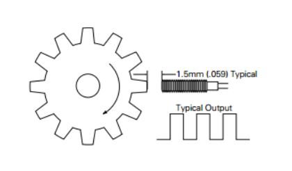
Figure 31 : Proposed setup configuration and typical output signal for a gear tooth speed sensor
Figure 31 shows a typical setup of this Hall Effect gear tooth sensor, in this case the gear will be replaced with a plastic disk. The motor is rated to operate at 500 rpm (9.17 Hz). The frequency at which it will sense the magnets is well below the maximum switching speed of the sensor.
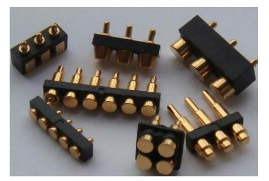
Figure 33: Example of proposed spring pin contacts to be embedded in the top frame for electrical connections and proximity sensing
The top frame proximity switches will ensure that the top frame is securely attached and prevent the walker from operating in the case that it’s not. The proximity switches will complete circuits that the Arduino will detect as a high digital input (5V). For a production version embedded spring contacts can be used for an easy user interface for attaching the top frame in a one step process. Figure 33 shows an example of these contacts.
ANALYTICAL CALCULATIONS
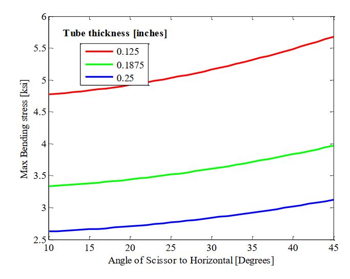
Figure 34 : The maximum flexure occurs at the fully upright position, this max bending stress is 5.7 ksi for square tube of thickness 0.125 inches with a side of 2 inches
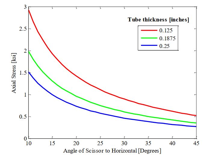
Figure 35 : Maximum axial stress occurs at the fully lowered position when lifting a person. The maximum axial stress for a 0.125 inch Aluminum tube is 2.97 ksi
The top section of the tube is in compression and the bottom in tension. A max von Mises stress of 8 ksi was seen with a patient load of 250 lbs. at 10 degrees. Figure 34 shows stress due to flexure. A maximum axial stress of 3 ksi is experienced by the lower tube and occurs at 10 degrees as seen in Figure 35.
ADAMS MODELING
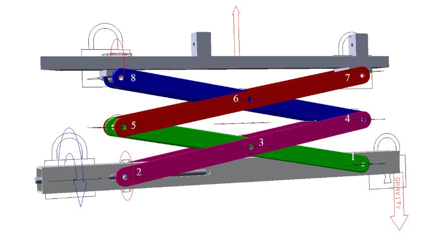
Figure 43: The half walker model showing the components connected. The icons show the forces
A rigid body dynamics model was created using MSC Adams by importing a parasolid CAD Model. It is important to note that each part had to have a unique part to prevent simulation failure. The scissor links were assigned stainless steel and the top frame aluminum for the inertia and mass calculations, listed in Table 17. Due to symmetry initially only a half model was simulated for joint forces as seen in Figure 43.
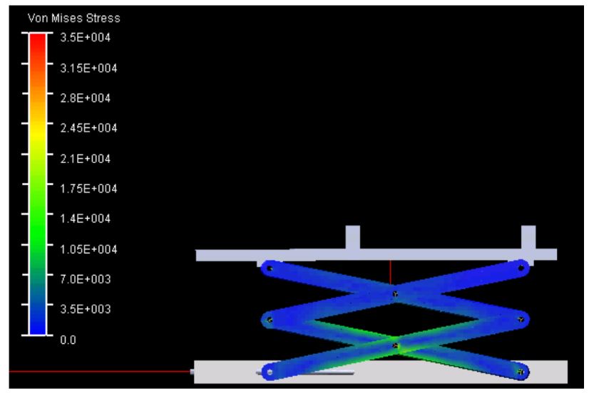
Figure 47 : The von Mises stress is around 10 ksi and is concentrated around joint 3 in the model
The Adams durability plug in was used to determine the stresses in the scissor links by converting these rigid bodies in to flexible components. The maximum von Mises stress experienced by the scissor links was 10 ksi, which is below the yield aluminum (40 ksi) for a maximum patient load of 250 lbs. Figure 47 shows the stress contour plot in this simulation aluminum was used as the material for scissor links and mid frame and lower tube.
FINITE ELEMENT ANALYSIS
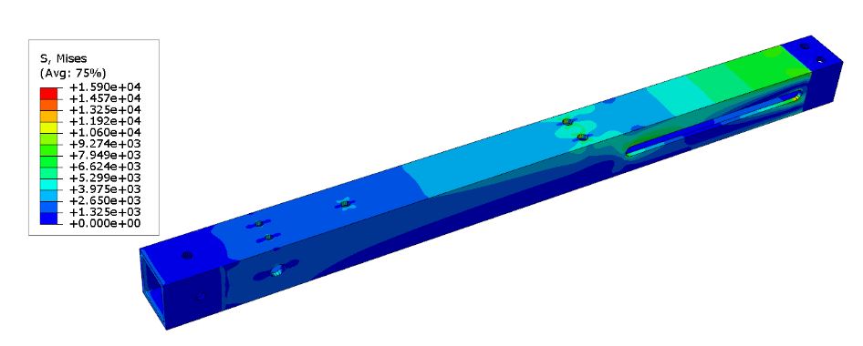
Figure 51: The von Mises Stress distribution in the lower tube, the stress of the lower tube is reduced with a n increase in wall thickness from 0.120 to 0.188 inches
To reduce the stress due to the holes, a thicker tube was selected, increasing the wall thickness from 0.120 to 0.188 inches reduced this stress by a factor of 2.4. Figure 51, shows the contour plot of this stress distribution.
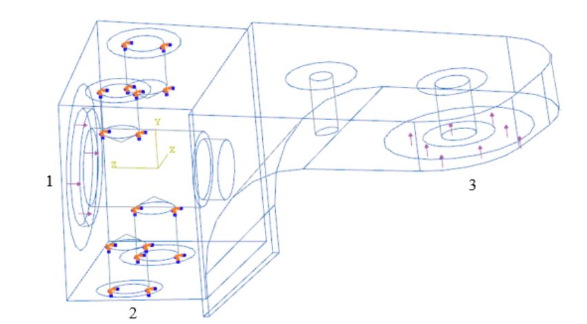
Figure 52 : The boundary conditions applied to the bearing block. A pressure load with total force of 1557 lbs. applied to region 1, with a ground reaction force of 200lbs applied to region 3
For the front bearing block the attachment holes were constrained and a pressure load applied to the region where the thrust bearing contacts the bearing block as well as the reg ion where front caster. Figure 52 annotates the load and boundary condition regions. A load of 1557 lbs. was applied to region 1, and a load of 200 lbs. was applied to region 3.
SAFETY REQUIREMENTS
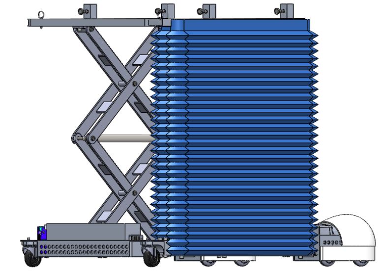
Figure 61 : The proposed bellowing would encompass all moving parts
Two types of pinch protection systems were evaluated for the walker; an active system that included tactile edge sensors (commonly used in machine guards) and passive system that comprised of physical barriers. Due to the added complexity and costs of an active system a physical barrier was specified in this design.
CONCLUSION
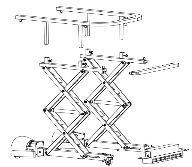
Figure 63 : The design allows the walker to be disassembled in to 5 pieces for transportation. The heaviest component is the scissor assembly with a weight of 35 lbs
A walker capable of lifting a 250 pound person from sitting to standing in under seven seconds was designed for easy manufacturability in a university machine shop. The walkers mass is 105 pounds, which is comparable to a hoist type of device. This design is modular to allow easy disassembly for easy transportation of the device. As seen in Figure 63 the walker can be disassembled in to 5 major pieces with no sub component weighing more than 35 pounds.
Source: California Polytechnic State University
Author: Pradipkumar